PICAXE Cheat Sheet AND Optimisations

PICAXE 08M2+ BASIC Commands
Full Programming Manual can be found in the PICAXE Editor 6 via Help button.
OUTPUT
HIGH or SWITCH ON Switch an output pin high ( on)
High 2 'turns pin 2 on
LOW or SWITCH OFF Switch an output pin low (off)
Low 3 'turns off pin 3
TOGGLE Toggle the hi/lo state of an output pin
Toggle 3 'changes pin 3 from high to low or low to high
PULSOUT Output a timed pin inverted pulse
Pulsout 0,3 'pin 0, 30 microsec
PWM Provide a pulse width modulation output
PWM 1, 20, 8 'pin 1,20/255 duty,8 cycles
SOUND Make sound(s) 0 =quiet, 255 = hiss.
Sound 4,(90,10) 'sound pin 4, ~4kHz,~100ms
LET PIN(S) Set multiple pin(s) at same time
Let pins = %00000101
INPUT
PULSIN Measure input pulse duration (uS)
Pulsin 4,0 ,w2 'pin 4 input, logic low triggered
READADC Read analog Pin (0 - 160) into a variable
Read 1, b2 'read pin 1 voltage on pin 1 into b2
TIME DELAY
PAUSE Wait up to 65535 ms ( 65.5 secs ) + ~1 ms o'hd.
Pause 100 ' pauses ~100ms =0.1s
WAIT Wait for up to 65 secs
Wait 3 'wait for 3 seconds
SLEEP 2.3 second low power delay (1 to 65535)
Sleep 3600 'sleep > 1 hr
NAP Short low power 20uA ( <2.3 secs)
Nap 3 'sleeps for 144ms
END Power down stop until reset
End 'indefinite power down sleep
I/O PIN CONTROL
OUTPUT Set a pin as an output
Output 1 'make pin 1 an output
INPUT Set a pin as an input
Input 4 'make pin 4 an input
REVERSE Reversethe I/O state of a pin
Reverse 4 'change pin 4 from OP > IP or IP > OP
LET DIRS = Simultaneously set all pin directions (1 = OP)
Dirs = %0000001011 'make pins 4, 2 & 0 outputs
Note: Pins 1 to 4 are INPUT by default on power up until set by program command controlled by an output command such as high low sound
PROGRAM FLOW
IF...THEN Jump to new program line depending on condition
If b3 < b2 then ledoff
FOR...NEXT Establish a for- next loop
For b2=0 to 100 step 2 'Counts even numbers
BRANCH Jump to address specified by output if in range ( akin to ON x GOTO )
GOTO Jump to a label
Goto loop ' Goes back to the main loop
GOSUB Jump to subroutine at address specified
Gosub test ' Heads to test subroutine
RETURN Returns to main prog. from gosub routine
Return ' Return to point just after subroutine call
Labels clarify and identify points in the program
FlashLED: ' Identify beginning of FlashLED module
VARIABLE MANIPULATION
LET Assigns a value to a variable, does limited L-R maths
Let w0 = b2 * 22 / 7 ' Pi
LOOKUP lookup indexed data specified by offset & store
lookup 1,(6,7,8) ' takes 7
LOOKDOWN Search values for a target's match number & store in variable. Akin to $strings
RANDOM Generate a pseudo-random number
Random b1 ' Randomise b1
SERIAL I/O
SERIN Serial data input
Serin 4 ,n2400,b1 ' read byte on pin 4 into b1 @24000bd
SERIN Serial data input - qualified
Serin 4 ,n2400,("A"),b1 ' read byte after A
SEROUT Serial data output ( to 2400bps)
Serout 0, n2400, (65) ' sends ASCII 65 (A)
INTERNAL EEPROM ACCESS
( Note this used for both prog. & data storage ! Care – since program overwriting may occur)
EEPROM Store data in EEPROM before download
eeprom 0,("hello") ' store from location 0 hello
READ Read data EEPROM into variable
Read 100,b2 ' get byte in address 101into b2
WRITE Write variable into data EEPROM
Write 101,b3 ' put byte b3 into address 101
MISCELLANEOUS
DEBUG Displays variable value on attached PC screen
Debug b0 ' read shows b0 value on VDU
REM Remarks, Semicolons (;) or apostrophe (') preceed remarks/comments, & also colons (:) as usual in BASIC
SYMBOL Assign a value to a new symbol name. symbol RED_LED = 7 ‚ symbol COUNTER = B0 Uses no extra memory space!
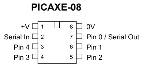
| LEG | PIN | NOTES |
|---|---|---|
| 1 | Plus Power | +Ve Power Supply, +3V to +5V |
| 2 | Serial | Input only for program download |
| 3 | Pin 4 | Input or Output |
| 4 | Pin 3 | Input only |
| 5 | Pin 2 | Input or Output |
| 6 | Pin 1 | Input or Output or Analogue input |
| 7 | Pin 0 | Output or program serial/debug out |
| 8 | Minus Power | -Ve Power supply (0V) |
 | ||
- 3 VDC from 2 x AA
alkaline battery in switched
battery box is the recommended power supply - Current draw = 600uA idle no load
- Current draw = 100uA sleep/nap no ld
- Digital out high = Supply –0.1V OC
- Digital out high = 12mA out to –ve
- Digital out low = 0.0 Volt OC
- Digital out low = 27mA in from +ve
- Digital In 1 = High >= 0.9 Volt
- Digital In 0 = Low <= 0.85Volt
- ADC In 0V=0, 1.5V=128, >2V=160(max)
- PWM Out 0 = 0V, 128=1.5V, 255=3V
- Download or install software
- Start programmer: Start>Programs>
Revolution Education>Program Editor - You may like to copy the start menu shortcut
to the desktop for easy access - If Needed install USB – Serial Adaptor using the
the correct supplied driver. - Start the program
- View>Options Change Mode to PICAXE-08
- Select Serial Port Tab and choose Com Port
- Click OK
Insert LED +ve (long lead) into the middle
socket (data to PICAXE pin 2) of the
programming lead. Insert the short lead into the outer
(return data to PC pin 1).
Press F8 to open the Serial Coms screen.
Type in some characters and click on the
send button. The LED will flash and data
should appear in the top window.
- At 3 volts the chip can’t be damaged.
- Test each new instruction by itself.
- Use debug to check your program.
- Forget about chip leg numbering as
soon as possible! Think software pins. Filename.bas = basic language program
- Filename.cad = flow chart program.
- Example *.bas and *.cad programs can be found:
File > Open > Samples
F1 Quick Short Syntax Help
F4 Simulate Flow Chart
F5 Convert Flow Chart to Basic
F5 Load Basic Program into PICAXE
F6 Re Activate Debug Screen
F8 Serial Communications Screen
F9 Data Logger Screen
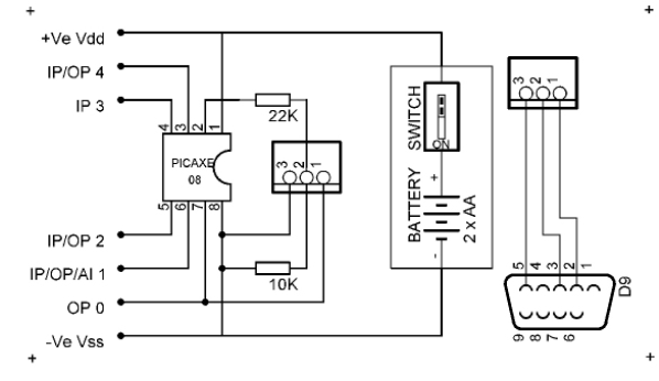
Quick Links for additional information about PICAXE.Typical Hookup
PICAXE Optimisations
Tips and Tricks for Making Your Code Fit
Program optimisation is an art, but based upon scientific principles and technical observations.
Download PDFBefore considering optimisations for PICAXE code, it is important to realise that most optimisations will make your program code less readable, less understandable, less maintainable, and harder to debug than unoptimised code.
It is therefore recommended that all but the simplest optimisations should be left until your code has been completed, tested and debugged. This may not however always be possible when you are running out of program code space before your code is finished. In such circumstances it is recommended to apply as few optimisations as possible to make your program code fit.
Unless there is a real need to perform optimisation it is often better practice to leave the code unoptimised. And if you do implement any optimisations it is wise to document what you have done, and why, in your program source code, if you wish to understand the code when you return to it at a later date, or pass it on to another PICAXE programmer.
Most of the lower-end PICAXE's are pretty constrained devices when it comes to the amount of program code which they can hold; quite often just 128 or 256 bytes of program which may have to be shared with EEPROM data. It can therefore be a challenge to make your program fit into the available space - There is nothing worse than adding a single line of code only to find that you have suddenly exceeded the maximum amount of memory available.
The art of making a program fit into the available space is called 'optimisation', and there are two sorts; optimising for speed of execution, and optimising for minimal program code space. The two are often mutually exclusive as a compact program, usually with loops, needs all those loops unrolling into repeated sequential code to gain a speed advantage, and vice-versa. For the PICAXE however, it is quite common that optimisations to reduce code space will also speed up the program because of the way the PICAXE holds its program in memory.
Unlike a traditional microcontroller where a single instruction takes multiple numbers of locations in program code memory, the PICAXE uses a system where the instructions are not of a fixed size. This means that the shorter the instructions it needs to use the more that can be fitted into the available code memory, and the shorter the instructions, the quicker ( in general ) they are to execute.
The optimisations detailed here are all designed to reduce the program code size and hopefully increase the speed of execution. Speed may not always be increased though because, if an instruction is placed into memory such that it overlaps two consecutive memory locations, and that's quite likely, then it will take slightly longer to execute. The loss of execution speed may be regained elsewhere by other optimisations which improve it, and it is a small price to pay to make the program fit which is often far more important than the raw execution speed.
Numbers
The first thing to know is that the larger the value of a constant ( a number ), the more program memory bits it will use; a 0 or 1 requires four bits, 2 to 15 requires seven bits, 16 to 255 require 11 bits while 256 to 65,535 require 19 bits. Using the smallest numbers you can may achieve great savings.
Suppose you want to take the inputs from Pin 6 and Pin 5 and turn these into a value in 'b0' of between 0 and 3. One obvious solution would be ...
b0 = pins & %01100000 / %00100000
It works, but the '%01100000' is a number which requires 11 bits in total to represent it. If we do the division before the '&' masking we can use ...
b0 = pins / %00100000 & %00000011
It still works, but because '%00000011' only requires seven bits, we just saved four bits ( over 30% ) which can be used elsewhere.
Pin Numbers
The size of numbers is also important when it comes to instructions which operate on input and output pins; "HIGH", "LOW", "PULSIN", "PULSOUT", "SERIN", "SEROUT" and others.
Using pins 0 or 1 adds just four bits to the instruction whereas using pins 3 to 7 adds seven bits. Designing your hardware so your most commonly referred to pins within the code are Pin 0 and Pin 1 can have a significant effect across a complete program.
Numbers in Variables
Variables require seven bits to represent themselves, so if you are using a large number a multiple number of times it can make sense to put that value into a variable and use the variable where the number would have been ...
w0 = w1 & $1000 + $1000
can be rewritten as ...
w2 = $1000
w0 = w1 & w2 + w2
Although the initial assignment into 'w2' adds extra code, the net result is a saving of bits. Of course, the more frequently a number is used, the greater the saving in total.
Optimising Variables
There are very few options for optimising variables. Unlike numbers they do not use different sized representations depending on the variable used.
The only real optimisation which can be achieved is in assignments where the variable being assigned to also appears as the first variable immediately on the right hand side of the '=' ...
b0 = b0 + b1
    b0 = b0 + 1
are more program code space efficient than ...
b0 = b1 + b0
    b0 = 1 + b0
Assignments using FOR
A rather clever trick, which can only be used in your program if you are not otherwise using FOR..NEXT loops is to replace simple assignments which have no mathematical operations to them with a 'FOR' statement ...
b0 = 29
    b1 = b0
Can be replaced by ...
FOR b0 = 29 TO 29 ' b0 = 29
    FOR b1 = b0 TO b0 ' b1 = b0
All the 'FOR' part of the FOR..NEXT loop does is to initialise what would be an index variable with the value which appears immediately after the '=', the value after the 'TO' is redundant and could actually be anything at all. The clever part of the FOR..NEXT loop is all associated with the 'NEXT', which we won't be using, but the 'FOR' part assignment is a lot shorter than the proper way of doing it.
There are two problems with this optimisation; firstly it is not easily seen that it is an optimisation and not some coding error without some additional commentary explaining it, and it will not work if you do need to use FOR..NEXT loops in your program, as the compiler is likely to complain when you do a Syntax Check or attempt a download.
Redundant Assignment Operations
It is important to remember that the PICAXE compiler performs very few optimisations itself, and it will generate code to do whatever you ask it to ...
b0 = 0 + 0 + 0 + 0 + 0
will generate four completely redundant additions of zero, even though they will not have any effect upon the value assigned to 'b0'. The same occurs if you divide or multiply by one and in a number of other cases.
While it is relatively easy to spot redundant operations such as the example above, it is much harder to spot them when named constants defined by 'SYMBOL' are used ...
SYMBOL y = b0
    SYMBOL x = b1
    SYMBOL M = 2
    SYMBOL C = 1

    y = M * x + C
In this case there is no redundancy, but if M were zero or one, or C were zero then there would be redundancy.
Named constants are a double-edged sword; while making your code more readable and modifiable, they can also have the unwanted side-effect of using up excess program space. The choice between using named constants or not is not an easy one to make.
Negative Numbers and Constant Arithmetic
Although the PICAXE deals only with positive numbers, two's complement arithmetic means that negative numbers can be represented, and are often useful as in the following code ...
GoUp:
        b0 = 1
        GOTO Go

    GoDown:
        b0 = 0 - 1 ' b0 = -1

    Go:
        b1 = b1 + b0
The PICAXE does not allow 'b0=-1' and this has to be derived by using 'b0=0-1' as in the above example. This uses an unnecessary 9 bits of program code. When we are subtracting one constant from another, we will end up with another constant, so by pre-calculating that result ( 0-1 is $FF in this case ) we can simply replace the 'b0=0-1' with the equivalent constant, 'b0=$FF'.
The same pre-calculations can be applied whenever the PICAXE is being instructed to perform constant arithmetic itself, for example ...
w0 = w0 * 2 * 1000 / 4
becomes ...
w0 = w0 * 500
This technique is commonly known as "Constant Folding".
There are special cases to be careful of ...
b0 = b0 * $8000 / $8000
In this example it would appear that multiplying by a number and then dividing by that same number is a pointless operation which achieves nothing, however there is much more to it than first meets the eye.
All arithmetic is performed using 16-bits, and a large multiplication, as above will cause a result greater than 16-bits. Those bits above the bottom 16-bits are lost, and this can often be used to great effect. The above code is actually a very poor way to do 'b0 = b0 & 1', and constant folding would not give the result expected.
The same issues can apply with division followed by multiplication ...
b0 = b0 / 4 * 4
This is equivalent to 'b0 = b0 & $FC', and again, constant folding will not give the result desired.
Conditional Assignments
Often you will want to set a variable's value depending upon some condition or other, in a pseudo design language ...
IF pin0 = 0 THEN
        b0 = $0F
    ELSE
        b0 = $F0
    END IF
Using the PICAXE programming language, a reasonable implementation of the example is as follows ...
IF pin0 <> 0 THEN SetToF0

    SetTo0F:
        b0 = $0F
        GOTO SetDone

    SetToF0:
        b0 = $F0

    SetDone:
This can be optimised to ...
b0 = $0F
        IF pin0 = 0 THEN SetDone
        b0 = $F0

    SetDone:
The same technique can be used when setting or clearing Digital Outputs but care must be taken to ensure that 'glitches' caused by setting the Output incorrectly before setting it correctly does not cause problems with the attached hardware ...
LOW 0
        IF b0 = 0 THEN SetIoDone
        HIGH 0

    SetIoDone:
Optimised FOR..NEXT loops
There is very little which can be done to optimise FOR..NEXT loops; they use a fairly large amount of program space, but then the equivalent inline code where a variable is initialised, incremented or decremented and a conditional branch to the start of a loop uses just the same amount.
The only significant savings can be made where a FOR..NEXT loop takes an index variable between two pre-defined numbers, which is the case with most ...
PrintSixteenStars:
        FOR b0 = 1 TO 16
            SEROUT TX_PIN, TX_BAUD, ("*")
        NEXT
        RETURN
The FOR..NEXT loop is defined as 'FOR b0 = 1 TO 16' because the loop needs to be executed sixteen times; loop 1, loop 2, and so on through to loop 16.
Because the index variable 'b0' is not actually used within the loop, and is effectively used as a simple count of how many times it has gone through the loop, it could equally be '11 TO 26' or '2 TO 17', but the optimum is '0 TO 15', because, as we know, the program code space taken up by numbers depends upon the value of the number and 0 and 1 use less program code than 2 and above, and 2 to 15 use less code space than 16 and above.
Although the change of the starting value from 1 to 0 makes no saving, changing 16 to 15 saves four bits.
It is not always easy to optimise the FOR.NEXT values, especially where the index value needs to be used within the loop, but you will be coding for maximum space saving if your FOR..NEXT loop starts with value 0, and failing that, at value 1.
Redundant GOTO RETURN's
Having a 'GOTO' to a 'RETURN' statement is wasteful as the GOTO can simply be replaced by a 'RETURN' ...
GOTO Finished

    Finished:
        RETURN
Redundant GOSUB RETURN's
A 'GOSUB' followed by a RETURN can simply be replaced by a 'GOTO' to the subroutine. Not doing so is wasteful in three of ways; it requires more code space, it takes longer to execute, and it eats into the number of GOSUB's you may be allowed to have in your program.
GOSUB MyRoutine
    RETURN
Should simply become ...
GOTO MyRoutine
Wasteful GOSUB Allocation
If you are using a PICAXE which can support 256 GOSUB's but are using only 16 or less, then you should configure the compiler to use just 16 GOSUB's as this will reduce the program code required for each GOSUB.
LOOKUP versus READ and EEPROM
The 'LOOKUP' command can, in some circumstances, be fairly program space hungry and can sometimes be implemented with less program memory used by using of 'READ' and 'EEPROM'. The two following code examples both turn a value of 0 to 3 held in 'b0' into a character "A" to "D" put into 'b1' ...
Convert:
        LOOKUP b0,("A","B","C","D"),b1
        RETURN

    Convert:
        READ b0,b1
        EEPROM 0,("A")
        EEPROM 1,("B")
        EEPROM 2,("C")
        EEPROM 3,("D")
        RETURN
Duplicated Textual Strings
It is worthwhile noting that specifying textual strings as opposed to individual characters makes no program space saving. In the above example, using 'EEPROM 0,("ABCD")' would save no program space at all.
Duplicated strings are however another entirely different matter, and are most likely to occur when using the 'SEROUT' command to send information to an LCD or PC ...
PlayerWins:
        SEROUT TX_PIN,TX_BAUD,("You are the winner")
        SEROUT TX_PIN,TX_BAUD,(CR,LF)
        RETURN

    ComputerWins:
        SEROUT TX_PIN,TX_BAUD,("I am the winner")
        SEROUT TX_PIN,TX_BAUD,(CR,LF)
        RETURN
Reasonably long duplicated strings may be removed into a separate, common routine while still producing a net saving of program space ...
PlayerWins:
        SEROUT TX_PIN,TX_BAUD,("You are")
        GOTO TheWinner

    ComputerWins:
        SEROUT TX_PIN,TX_BAUD,("I am")

    TheWinner:
        SEROUT TX_PIN,TX_BAUD,(" the winner")
        SEROUT TX_PIN,TX_BAUD,(CR,LF)
        RETURN
Consecutive SEROUT's
The 'SEROUT' command is fairly program space hungry and large savings can be made by combining consecutive 'SEROUT' commands into one ...
TheWinner:
        SEROUT TX_PIN,TX_BAUD,(" the winner")
        SEROUT TX_PIN,TX_BAUD,(CR,LF)
        RETURN
becomes ...
TheWinner:
        SEROUT TX_PIN,TX_BAUD,(" the winner",CR,LF)
        RETURN
Duplicated Code
As with removing duplicated strings above, the same can be applied to any duplicated code ...
RoutineOne:
        w0 = w0 * 2
        w1 = w1 + 1000
        RETURN

    RoutineTwo:
        w0 = w0 * 2
        w1 = w1 - 1000
        RETURN
The 'w0=w0*2' and RETURN are common to both routines, and as the assignment to 'w1' is not dependant upon 'w0' the two routines can be re-ordered and optimised ...
RoutineOne:
        w1 = w1 + 1000
        GOTO CommonCode

    RoutineTwo:
        w1 = w1 - 1000

    CommonCode:
        w0 = w0 * 2
        RETURN
SEROUT Pin Numbers
As mentioned earlier; referencing pins 0 and 1 uses less program code than any other pins, so if you have a number of 'SEROUT' statements it makes sense to design your hardware so that they are all reference Pin 0 or Pin 1 wherever possible.
Redundant Code
As the PICAXE will generate code for redundant operators during assignments, it will also generate code for redundant statements; those statements which are never executed.
If you have any statements which are there because they, "may be used later", but are not presently used, then it is wise to comment them out of the code until they are needed. It can often be difficult to spot redundant code, especially when it is a subroutine which is never called, and was written when you thought you may need it.
The END Statement
Do not put an 'END' statement as the last statement of your source code; the compiler will always automatically insert one at the end of your program whether it is needed or not.
PICAXE is a trademark of Revolution Education Ltd. These PICAXE pages are produced entirely independently of Revolution Education Limited and may not reflect the opinion of Revolution Education Limited or its agents. The information provided is based upon and derived from information published by Revolution Education Limited, other sources of PICAXE information and the author's own experiments and prior experience. The views expressed by the author do not necessarily represent those of Revolution Education Limited or its agents. While every effort has been made to ensure that the information on these PICAXE pages is accurate and correct, the author can accept no responsibility for any errors or omissions which do occur. The information provided is used entirely at your own risk.
First published Copyright (C) 2004 - The Happy Hippy on Thursday the 25th of February, 2004 at 14:38:14
Last upload was on Sunday the 25th of July, 2004 at 16:36:45
Edited and used with consent for Ralph Bayer VE3XRM on Thursday the 19th of October, 2023 at 11:13:14
263 Page Views [1]