MAX7219 8x8 LED Matrix ATtiny85
Code to Bit-Bang the MAX7219 chip to display a BMP image.
Photos
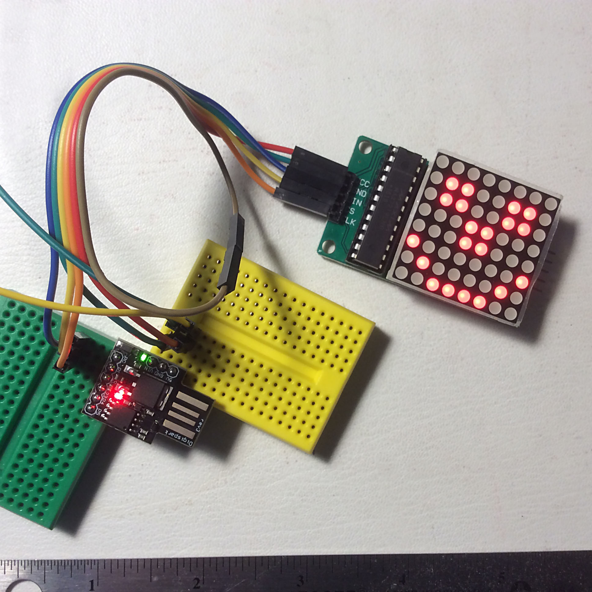
Photo is for illustrative purposes only. Please refer to the description.
Code Sample
To copy code:
Hover over the right top corner of the code panel.
Click COPY button, the code will be COPIED to the clipboard.
/*
Here's some code for testing ::: 8) Used Arduino IDE 1.6.12
Runs on Trinket or DigiSpark controller(ATtiny85)
or change the port pins to use Arduino UNO.
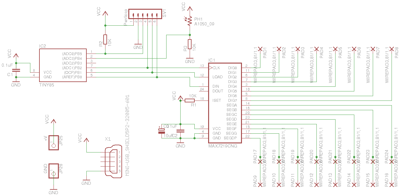
One MAX7219 connected to an 8x8 LED matrix. Bit-Bangs the chip.
Origina�l Code Base: https://halfbyteblog.wordpress.com/2015/11/29/using-a-max7219-8x8-led-matrix-with-an-attiny85-like-trinket-or-digispark/
Sketch uses 330 bytes (5%) of program storage space. Maximum is 6,012 bytes.
Global variables use 24 bytes of �dynamic memory.
Modifed and fixed some coding errors - rhb.20220905 -
*/
#include <util/delay.h>
#define MAX7219_DIN PB0 // DIN, pin 3 on the MAX7219 Board
#define MAX7219_CS PB1 // CS, pin 4 on the MAX7219 Board
#define MAX7219�_CLK PB2 // CLK, pin 5 on the MAX7219 Board
#define DATA_HIGH() PORTB |= (1 << MAX7219_DIN)
#define DATA_LOW() PORTB &= ~(1 << MAX7219_DIN)
#define CS_HIGH() PORTB |= (1 << MAX7219_CS)
#define CS_LOW() PORTB &= ~(1 << MAX7219_CS)
�
#define CLK_HIGH() PORTB |= (1 << MAX7219_CLK)
#define CLK_LOW() PORTB &= ~(1 << MAX7219_CLK)
#define INIT_PORT() DDRB |= (1 << PB0) | (1 << PB1) | (1 << PB2)
/*
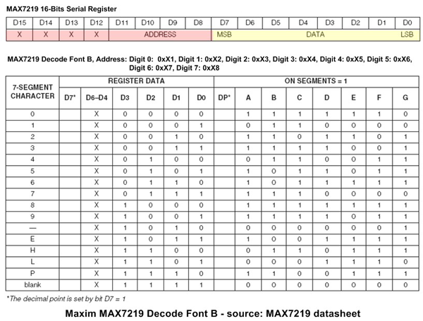
The same code can control an 8-digit 7-segment display.
uint8_t ZERO = �0b01111110;
uint8_t ONE = 0b00110000;
uint8_t TWO = 0b01101101;
uint8_t THREE = 0b01111001;
uint8_t FOUR = 0b00110011;
uint8_t FIVE = 0b01011011;
uint8_t SIX = 0b00011111;
uint8_t SEVEN = 0b01110000;
uint8_t EIGHT = 0b01111111;
uint8_t �NINE = 0b01110011;
uint8_t DOT = 0b10000000;
unit8_t BLANK = 0b00000000;
I wouldn't do it this way. The chip can decode BCD to 7-segment.
*/
uint8_t smile[8] = {
0b00000000,
0b01100110,
0b01100110,
0b0001100�0,
0b00011000,
0b10000001,
0b01000010,
0b00111100};
uint8_t sad[8] = {
0b00000000,
0b01100110,
0b01100110,
0b00011000,
0b00011000,
0b00000000,
0b0011110�0,
0b01000010,
};
void spi_send(uint8_t data) {
uint8_t i;
for (i = 0; i < 8; i++, data <<= 1) {
CLK_LOW();
if (data & 0x80)
DATA_HIGH();
else
DATA_LOW();
CLK_HIGH();
}
}
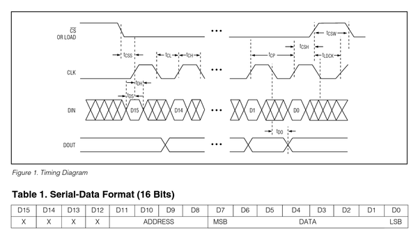
void max7219_writec(uin�t8_t high_byte, uint8_t low_byte) {
CS_LOW();
spi_send(high_byte);
spi_send(low_byte);
CS_HIGH();
//CLK_LOW(); // might not be needed rhb.
}
void max7219_clear(void) {
uint8_t i;
for (i = 0; i < 8; i++) {
max7219_writec(i+1�, 0);
}
}
void max7219_init(void) {
INIT_PORT();
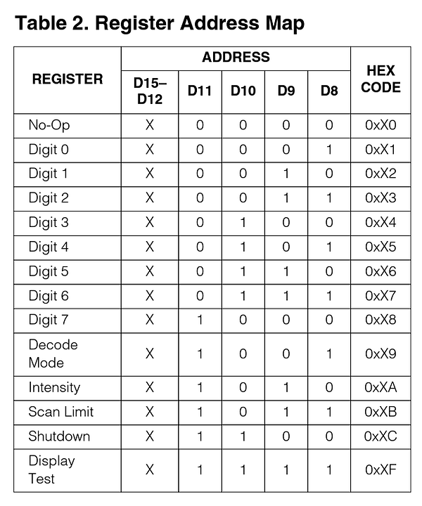
// Decode mode: none
max7219_writec(0x09, 0);
// Intensity: 3 (0-15)
max7219_writec(0x0A, 1);
// Scan limit: All 'digits' (rows) on
max7219_writec(0x0B, 7);
// Shutdown regis�ter: Display on
max7219_writec(0x0C, 1);
// Display test: off
max7219_writec(0x0F, 0);
max7219_clear();
}
uint8_t display[8];
void update_display(void) {
uint8_t i;
for (i = 0; i < 8; i++) {
max7219_writec(i+1, display[i]);
�
}
}
void image(uint8_t im[8]) {
uint8_t i;
for (i = 0; i < 8; i++)
display[i] = im[i];
}
void set_pixel(uint8_t r, uint8_t c, uint8_t value) {
switch (value) {
case 0: // Clear bit
display[r] &= (uint8_t) ~(0x80 >> c)�;
break;
case 1: // Set bit
display[r] |= (0x80 >> c);
break;
default: // XOR bit
display[r] ^= (0x80 >> c);
break;
}
}
int main(void) {
uint8_t i;
max7219_init();
while(1) {
�image(sad);
update_display();
_delay_ms(1000);
image(smile);
update_display();
_delay_ms(1000);
}
}Schematic
Video
Bill of Materials (BOM)
Comments
Links
posted/edited by Ralph [VE3XRM] | 20250718 | 21:56
NOTE:
These projects require simple skills in electronics assembly and programming.
Minimal instructions might be provided.
These projects require simple skills in electronics assembly and programming.
Minimal instructions might be provided.
103 Page Views [1]